
Share
What Causes Overheating in a Distribution Board?

What Causes Overheating in a Distribution Board?
A distribution board is expected to get warm under normal operating conditions. It carries current, contains protective devices, and may be installed in an electrical room where ambient temperatures are already elevated. Overheating becomes a concern when heat is concentrated at a terminal, breaker, busbar joint, cable entry, or enclosure area; when it rises beyond the equipment’s intended thermal conditions; or when it develops over time without an obvious change in demand.
The question is not simply, “Is the board hot?” A more useful question is: where is the heat originating, and what electrical or installation condition is causing it? A hot main breaker may point to overload, while a single hot outgoing terminal may indicate a loose connection. A generally warm enclosure can be related to poor ventilation or an undersized board installed in a confined riser. These distinctions matter because excessive temperature accelerates insulation aging, degrades contacts, increases resistance, and can eventually lead to nuisance tripping, equipment failure, arc faults, or fire.
For facility managers, MEP contractors, panel builders, and procurement teams, a distribution board should be treated as part of a wider electrical path: transformer or incoming supply, feeder cable, switchgear, busbar system, protective device, load circuit, and surrounding environment. A fault in any part of that path can appear as heat inside the board.
Heat Usually Starts with Resistance, Current, or Poor Heat Dissipation
Electrical heating is often explained by the relationship between current and resistance. When current passes through a conductor or connection with resistance, energy is released as heat. A small increase in contact resistance can become serious when a circuit carries high current for long periods. This is why a connection that looks acceptable during a visual inspection can still become a thermal weak point under load.
A distribution board also has limited capacity to reject heat. Internal spacing, enclosure design, device arrangement, cable bending space, ventilation openings, ambient temperature, and the presence of adjacent heat-producing equipment all affect its operating temperature. The board may have been suitable when installed, then become thermally stressed after later tenant fit-outs, additional HVAC equipment, EV charging loads, server racks, kitchen appliances, pumps, or process machinery were added.
In practice, overheating is often cumulative. A slightly loose termination generates heat. Heat causes expansion and contraction. Repeated thermal cycling can further reduce contact pressure, creating more resistance and still more heat. This feedback loop is one reason an apparently minor defect should not be ignored.
Loose, Damaged, or Incorrectly Terminated Connections
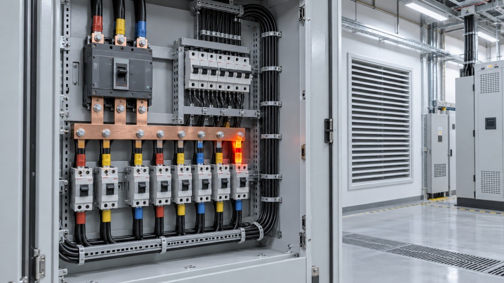
Loose terminals are among the most common causes of localized overheating. They can occur at incoming lugs, neutral bars, earth bars, breaker terminals, busbar connections, cable joints, and branch circuit terminations. A conductor may be inadequately tightened, tightened with an unsuitable tool, installed without the correct torque, or disturbed during maintenance. The issue is not limited to poor workmanship: copper and aluminum conductors can behave differently under thermal cycling, and incompatible connector or conductor combinations can create long-term reliability problems.
Other termination defects include damaged strands, insufficient conductor insertion depth, incorrect lug size, degraded crimping, oxidation, contamination, or use of a conductor type not approved by the terminal manufacturer. Fine-stranded flexible conductors, for example, may need preparation methods appropriate to the connector design. A terminal intended for one conductor class should not be assumed suitable for every cable construction.
Warning signs tend to be specific rather than subtle: discoloration around a lug, a browned insulation sleeve, brittle cable insulation, softened plastic near a breaker terminal, or a distinctive overheated electrical smell. By the time these signs are visible, the underlying connection may already require urgent professional assessment.
Overloaded Circuits and a Board That Has Outgrown Its Original Duty
Overload is different from a loose connection, although both can cause heating. An overloaded circuit carries more current, or carries elevated current for longer, than the system was designed to accommodate. The resulting heat may affect the breaker, cable, busbar, terminal, and enclosure together. Protective devices are intended to respond to overcurrent, but repeated loading close to equipment limits can still create high operating temperatures and shorten component life.
The problem is frequently introduced by operational change rather than by a single installation error. A commercial floor initially designed for lighting and small-power loads may later support dense workstations, supplementary cooling, pantry equipment, IT loads, or localized electric heating. In industrial and logistics facilities, motors, compressors, conveyors, and charging equipment can alter the load profile considerably. In residential towers, simultaneous evening demand can expose insufficient diversity assumptions or poorly balanced phase allocation.
A board’s rating should never be assessed from the main incomer alone. Engineers need to review feeder cable ampacity, protective device coordination, busbar capacity, enclosure temperature-rise characteristics, actual demand, diversity assumptions, and ambient installation conditions. A larger breaker is not a remedy for a hot circuit unless the entire downstream circuit has been properly evaluated for the new duty.
Unbalanced Three-Phase Loads and Neutral Problems
Three-phase distribution boards are particularly vulnerable to poor load balancing. When one phase consistently carries substantially more load than the others, that phase’s breaker pole, conductor, busbar section, and connections will run hotter. The issue may be missed if a site only checks total building demand rather than phase-by-phase current.
Modern buildings can make this more complicated. Non-linear loads such as some electronic power supplies, LED drivers, IT equipment, variable-speed drives, and UPS-supported systems may introduce harmonic currents. Depending on the system arrangement and load characteristics, harmonic effects can increase heating in neutrals, conductors, transformers, and distribution equipment. This does not mean every electronic load will overheat a board, but it does mean that load measurement should go beyond a single headline current reading when a recurring thermal issue is being investigated.
A hot neutral terminal deserves careful attention. It may result from a loose neutral connection, phase imbalance, inappropriate neutral sizing for the actual load profile, or a combination of these factors. Diagnosis should be carried out by qualified personnel using suitable measurement and safety procedures, not by tightening live components based on appearance alone.
Inadequate Ventilation and High Ambient Temperature
A properly assembled board can still operate too hot if the installation environment prevents heat from escaping. Common conditions include a board mounted in a small unventilated electrical closet, a recessed enclosure with little air movement, blocked ventilation paths, direct solar exposure, or a room shared with boilers, pumps, compressors, or other heat-generating equipment. Dust accumulation can further reduce airflow and coat insulating surfaces.
The ambient temperature around the board matters because device ratings are generally linked to stated reference conditions in manufacturer documentation and applicable product standards. When the surrounding temperature is higher than expected, protective devices and conductors may need derating or a different installation approach. The same board that operates acceptably in a ventilated technical room may run too hot in a sealed rooftop enclosure during summer conditions.
Ventilation should be considered as an engineered decision, not merely a matter of cutting openings in an enclosure. Changes can affect ingress protection, contamination exposure, fire compartmentation, and internal temperature performance. Where forced ventilation or air conditioning is used, maintenance of filters and airflow paths becomes part of electrical reliability planning.
Undersized, Poorly Selected, or Aging Components
Distribution boards are assemblies, and their thermal performance depends on compatible components. A board may have a suitable enclosure but inadequate internal busbars. It may contain breakers that are technically rated for the circuit but tightly packed in a way that limits heat dissipation. It may have cable entries that force excessive bending, crowd conductors, or transfer heat from heavily loaded feeders into the enclosure.
Material selection also matters. Copper and aluminum alloy conductors have different installation and connection considerations. Busbar geometry, joint design, plating, contact pressure, and surface condition can all influence resistance and temperature rise. These are not details to leave entirely to price comparison when equipment will operate near continuous high load.
Ageing introduces another layer of risk. Breaker contacts can wear, springs and terminals can lose performance, insulation can harden, and corrosion can develop in humid or chemically exposed environments. Repeated fault interruption may also affect devices that appear physically intact. A board that has served reliably for years should not be assumed to have the same thermal margin after operational conditions have changed.
How to Distinguish the Likely Cause
The heat pattern provides useful clues. Thermal imaging, performed by competent personnel under meaningful operating load, is widely used because it can reveal abnormal temperature differences without dismantling energized equipment. It is a screening tool, not a complete diagnosis: emissivity, viewing angle, load level, reflective surfaces, and comparison points all influence interpretation.
Other evidence should be gathered alongside a thermal survey: load logs, breaker trip history, maintenance records, design drawings, recent fit-out changes, cable schedules, and equipment manufacturer instructions. A temperature reading without context can be misleading. A warm component at high, stable, expected load may be less concerning than a localized hotspot on a lightly loaded circuit.
Prevention Is a Design and Maintenance Discipline
The most effective prevention begins before energization. Panel builders and contractors should use compatible, properly rated components; follow approved assembly practices; observe terminal torque requirements; provide correct conductor preparation; maintain suitable cable routing; and allow for realistic load growth where the project brief supports it. Design review should consider short-circuit performance and protection coordination as well as normal-load thermal behavior.
During operation, periodic inspections should be based on criticality, environment, load volatility, and maintenance strategy. High-rise buildings, hospitals, data-intensive workplaces, industrial facilities, and sites with continuous operations may justify more frequent condition monitoring than lightly loaded, stable installations. Infrared surveys, targeted torque verification during planned shutdowns, cleaning, phase-load review, and inspection of ventilation paths can identify developing defects before they become disruptive.
IoT-enabled energy and condition monitoring can add value where loads vary significantly or boards are widely distributed across a portfolio. It is most useful when alarms are tied to a clear response process. Collecting temperature or current data without defining thresholds, escalation responsibility, and maintenance actions can create a false sense of control.
A Practical Approach to Thermal Risk
When a distribution board overheats, replacing the visibly hot component may not solve the problem. The right response is to identify whether the cause is a connection defect, excessive demand, uneven phase loading, ambient heat, unsuitable assembly, or deterioration elsewhere in the circuit. In many cases, more than one condition is present.
For projects involving switchgear, busbars, fire-rated cables, cable containment, and lifecycle maintenance, Global Building Electrical & Fluid Systems (BEFS) frames thermal reliability as part of a connected MEP risk picture. The quality of a termination, the layout of a panel, the route of a feeder, and the operating environment all affect how safely power is distributed. Before approving a corrective action or a replacement board, review the actual load profile, equipment documentation, installation conditions, applicable local requirements, and the maintenance evidence available. That is usually more valuable than treating heat as an isolated fault.
Power Distribution Architect
Related News
- 00
0000-00
How to Structure SLAs and Data Ownership Terms With a Building IoT Monitoring Supplier - 00
0000-00
What Causes Overheating in a Distribution Board? - 00
0000-00
Are Distribution Boards Interchangeable Across IEC Projects? - 00
0000-00
Why Do Circuit Breakers Trip After Commissioning? - 00
0000-00
How to Choose Circuit Breakers for Critical Loads
Weekly Insights
Stay ahead with our curated technology reports delivered every Monday.