
Share
Are Distribution Boards Interchangeable Across IEC Projects?

Are distribution boards interchangeable across IEC projects? Usually, no. IEC-based design principles create a common framework, but they do not make every board physically, electrically, or legally compatible.
For EPC teams, contractors, manufacturers, and procurement managers, the practical question is whether a proposed board matches the project duty, installation conditions, protection scheme, and local approval requirements.
A distribution board can look comparable on a supplier datasheet yet introduce safety, coordination, maintenance, or acceptance risks once installed in another country or building type.
The correct approach is not to ask whether two boards meet IEC standards generally. It is to verify whether each board meets the exact technical schedule.
Why IEC Compliance Does Not Make Distribution Boards Automatically Interchangeable
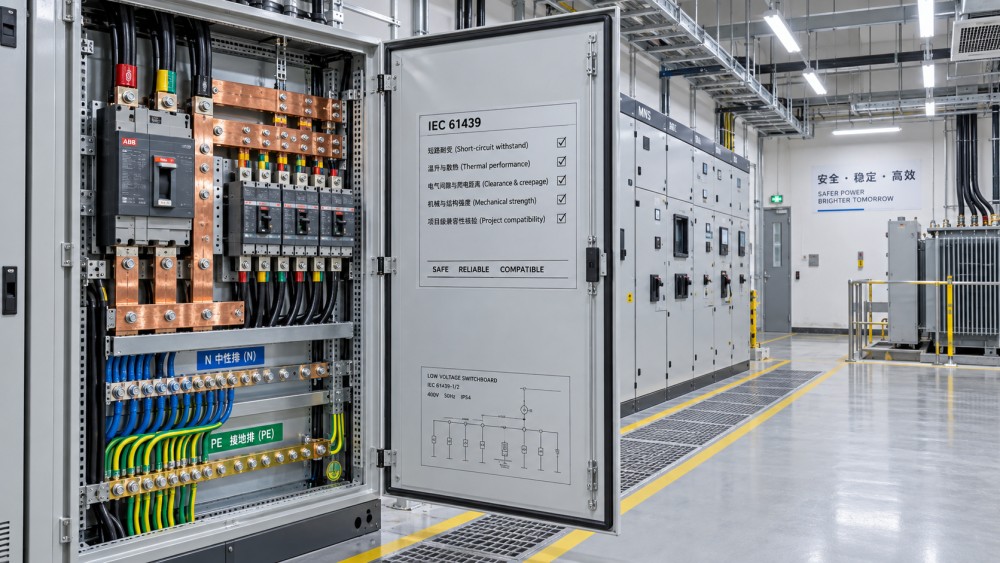
IEC standards establish recognized rules for safety, performance, testing, construction, and documentation. They provide a valuable common language for international building electrical projects and supplier evaluation.
However, IEC compliance is not a single universal product passport. Different distribution boards can comply with different standard editions, assemblies, ratings, test arrangements, and manufacturer limitations.
Most low-voltage distribution boards are evaluated under IEC 61439, while installed electrical systems may be designed around IEC 60364 principles and national electrical regulations.
IEC 61439 addresses assemblies, including temperature-rise performance, dielectric properties, short-circuit withstand capability, protective circuit continuity, clearances, creepage distances, and mechanical operation.
That does not mean every IEC 61439 assembly can replace another. The declared design verification applies only within the manufacturer's documented assembly configuration and operating conditions.
A board designed for a commercial floor may not suit an industrial plant, hospital, data center, high-rise riser, marine facility, or outdoor utility installation.
Interchangeability therefore depends on engineering equivalence, not on a shared IEC reference printed on product labels, catalogues, tender documents, or conformity declarations.
Procurement teams should also distinguish between component compliance and assembly compliance. Certified circuit breakers, busbars, enclosures, and meters do not automatically create a compliant final assembly.
The panel builder must show that selected devices, mounting systems, busbar layouts, internal conductors, terminals, and enclosure arrangements remain within the verified design rules.
Start With the Electrical Duty, Not the Board Dimensions
The first compatibility test is electrical duty. A replacement or standardized distribution board must carry, protect, and isolate the actual loads expected throughout normal operation.
Rated current is the starting point, but it is not enough. Engineers must consider diversified demand, future expansion, ambient temperature, grouping effects, harmonic content, and ventilation constraints.
A 250 A board may appear equivalent to another 250 A board. Its usable capacity can differ significantly because of busbar material, enclosure size, device spacing, and temperature-rise limits.
Thermal performance is especially important in compact electrical rooms. High ambient temperatures, poor air circulation, solar exposure, and adjacent heat sources can reduce practical loading margins.
Where non-linear loads are substantial, neutral current requires specific attention. LED drivers, variable-speed drives, UPS systems, office equipment, and data loads can create elevated harmonic currents.
A board with an undersized neutral bar or unsuitable neutral arrangement may perform acceptably in a simple lighting circuit but fail in a digitally intensive commercial building.
The incoming supply configuration must also match. Confirm nominal voltage, frequency, phase arrangement, neutral requirement, earthing method, and permitted voltage tolerances before approving any substitution.
Common IEC project configurations include 400/230 V three-phase four-wire networks, but regional practices and project specifications can vary regarding neutral treatment and supply arrangements.
Board dimensions should be reviewed after electrical duty. Physical fit matters, yet a board that fits a wall recess but cannot safely manage available load is not interchangeable.
Short-Circuit Withstand Is Often the Decisive Check
Short-circuit performance is one of the most frequently underestimated selection factors. The board must withstand and safely manage the prospective fault current at its installation point.
Available fault current can differ sharply between projects, even where the voltage and rated current appear identical. Transformer size, cable length, generator contribution, and upstream switchgear all matter.
Engineers should calculate or obtain the prospective short-circuit current at the distribution board incomer. This value must be compared with the assembly's declared short-circuit capability.
Relevant declarations may include conditional short-circuit current, rated short-time withstand current, rated peak withstand current, or a tested protective-device combination with specified limitations.
A downstream board may have a lower fault duty because feeder impedance limits current. A board installed near a large transformer can face significantly higher mechanical and thermal stress.
Replacing a board without reviewing fault duty can invalidate the original protection strategy. The proposed board may rely on an upstream breaker that is not present or unsuitable.
Coordination between upstream and downstream protective devices must also be checked. Selectivity, cascading, back-up protection, and energy limitation depend on documented manufacturer data rather than assumptions.
Mixing breakers from different manufacturers may be technically possible, but published coordination tables often no longer apply. This creates uncertainty during fault studies and commissioning reviews.
For critical facilities, ask for the short-circuit calculation, protective-device settings, time-current curves, selectivity evidence, and relevant assembly verification documents before making a replacement decision.
Busbar Configuration Determines More Than Current Capacity
Busbar design directly affects thermal behavior, fault withstand, maintenance access, future extension, and internal segregation. Similar cabinet sizes can contain very different busbar systems.
Copper and aluminum busbars should not be treated as equivalent solely by nominal current rating. Material conductivity, joint design, plating, contact pressure, and oxidation management influence long-term performance.
Verify phase, neutral, and protective earth bar sizes separately. In some systems, the neutral is full-sized, oversized, reduced, or arranged through a dedicated isolated bar.
The earthing arrangement is equally important. TN-S, TN-C-S, TT, and IT systems impose different design expectations for neutral-earth separation, protective conductor routing, monitoring, and fault protection.
A board configured for TN-S may not be suitable for a project requiring an IT system, particularly where insulation monitoring, insulated neutral arrangements, or continuity-of-service requirements apply.
Busbar access also affects lifecycle operations. Facilities teams need clear procedures for isolation, torque checks, infrared inspections, cleaning, extension work, and replacement of protective devices.
In high-rise projects, rising-main interfaces require special scrutiny. Incoming terminals, cable bending space, busbar trunking connections, gland plates, and fire compartment boundaries may differ by manufacturer.
Do not assume a board designed for cable-fed installation can directly accept a busbar trunking feed. Mechanical interfaces and fault-rated connection arrangements require manufacturer confirmation.
Enclosure Ratings Must Match the Real Installation Environment
Enclosure protection is another reason distribution boards are not interchangeable across IEC projects. The location can change risks from dust, water, corrosion, impact, heat, and unauthorized access.
Ingress protection ratings should be selected according to actual exposure. An IP30 indoor board may suit a dry electrical closet but not a basement pump room or external service area.
Higher IP ratings can also affect heat dissipation. A sealed enclosure may need lower loading, larger dimensions, forced ventilation, or different component spacing to control internal temperatures.
Mechanical impact resistance may be important in car parks, logistics areas, schools, workshops, public corridors, and plant rooms where equipment could be struck during operation.
Corrosive environments demand more than a stainless-steel label. Coastal air, chemical vapors, wastewater treatment conditions, and humid basements can affect hinges, fasteners, terminals, coatings, and internal connections.
Check enclosure material, coating system, gasket design, cable-entry sealing, drainage provisions, condensation management, and manufacturer environmental limits before transferring a board design between regions.
Outdoor distribution boards also require review of ultraviolet resistance, solar gain, rain exposure, flood elevation, ventilation strategy, and local utility or civil protection requirements.
Fire-related requirements should be assessed separately. Depending on location, projects may require specific fire compartment interfaces, smoke control provisions, emergency circuit separation, or fire-rated installation systems.
Local Regulations and Approval Routes Can Override a Generic IEC Approach
IEC standards are widely recognized, but local legislation, authority requirements, utility rules, insurance conditions, and client specifications can impose additional obligations beyond the base standard.
A board acceptable in one IEC-oriented market may require local certification, language-specific labeling, marking changes, metering interfaces, utility seals, or approved component brands elsewhere.
National deviations matter because installation practices differ. Requirements for residual current protection, surge protection, arc fault detection, emergency isolation, fireman switches, and circuit identification are not universal.
Projects governed by British, European, Middle Eastern, Asian, African, or local municipal specifications may reference IEC documents while applying different acceptance procedures and prescriptive requirements.
Exporters should avoid promising universal interchangeability based on CE marking or IEC test reports alone. The relevant question is whether documentation supports the destination project's stated compliance pathway.
Procurement documents should define applicable standards, editions, national regulations, certification bodies, test evidence, labeling language, commissioning records, and authority inspection responsibilities from the outset.
This reduces late-stage substitution disputes. It also prevents a contractor from installing an apparently equivalent board that fails final inspection because project-specific documentation is incomplete.
Replacement Projects Require More Checks Than New Installations
Replacing an existing distribution board is usually more complex than selecting one for a new build. The installed system may contain undocumented modifications and legacy protection arrangements.
Before replacement, conduct a site survey covering incoming cables, feeder sizes, existing loads, spare ways, fault levels, earth continuity, cable routes, access clearances, and shutdown constraints.
Legacy boards may use obsolete breaker frames, nonstandard rail systems, unusual busbar spacing, or unavailable accessories. Direct device replacement may be impossible without replacing the complete assembly.
Existing circuits should be assessed for insulation condition, conductor sizing, protective conductor continuity, polarity, identification, and suitability for updated protective-device settings before re-energization.
Physical installation constraints can create hidden cost. Wall openings, plinths, cable trench entries, top or bottom cable access, lifting routes, and door swing clearances affect replacement feasibility.
For occupied buildings, continuity planning is essential. Hospitals, hotels, offices, factories, and data facilities may require temporary power, phased transfer, weekend work, or redundant supply arrangements.
Older facilities may also have asbestos, restricted access, limited drawings, or energized adjacent equipment. These risks should be priced before a supposedly standardized board is approved.
A Practical Interchangeability Checklist for Procurement and Engineering Teams
A disciplined review process helps teams distinguish a true equivalent from a superficial substitution. Begin by comparing the approved technical schedule against the proposed assembly's verified declaration.
Confirm rated operational voltage, frequency, rated current, incoming arrangement, outgoing circuit count, spare capacity, phase balance assumptions, neutral sizing, and protective earth configuration.
Verify prospective short-circuit current, declared assembly withstand rating, breaker interrupting capacity, protective-device coordination, discrimination requirements, and any limits on upstream protection devices.
Review form of internal separation where specified. Segregation between busbars, functional units, terminals, and cable spaces can affect safety, maintenance procedures, and continuity during servicing.
Compare enclosure dimensions, IP rating, impact resistance, corrosion resistance, ambient operating range, mounting method, cable entry arrangements, and required clearances for operation and maintenance.
Check metering, communications, energy monitoring, building management interfaces, current transformers, remote trip functions, surge protection, and alarm contacts where smart building operation is required.
Request assembly drawings, single-line diagrams, bill of materials, type-test or design-verification evidence, routine-test records, torque requirements, installation instructions, and warranty conditions.
Finally, confirm local approval obligations and obtain written acceptance from the responsible designer, consultant, authority, or client representative before ordering a substituted distribution board.
When Standardization Creates Value and When It Creates Risk
Standardizing distribution boards across a portfolio can deliver tangible benefits. Buyers can reduce supplier complexity, improve spare-parts availability, simplify technician training, and consolidate service agreements.
Manufacturers may also provide better commercial terms when projects use repeatable configurations. Standardized panel architectures can shorten design cycles, improve documentation quality, and support prefabricated construction.
However, standardization should be based on modular, verified platform designs rather than one fixed board imposed on every installation. Electrical duty and local conditions must remain decisive.
A practical strategy uses approved configuration families. For example, a company may standardize breaker brands, meter protocols, enclosure finishes, terminal conventions, and documentation templates.
Within that framework, current ratings, fault levels, busbar systems, enclosure protection, circuit arrangements, and local compliance features can be adapted for each project.
This approach protects procurement efficiency without forcing unsuitable equipment into high-risk applications. It also helps facility teams recognize equipment while retaining project-specific engineering integrity.
For multinational developments, maintain a controlled technical specification with mandatory parameters, optional modules, regional deviations, accepted evidence formats, and a clear approval process for substitutions.
Conclusion: Interchangeability Must Be Proven at Project Level
Distribution boards are not automatically interchangeable across IEC projects, even when both products cite the same standards and appear similar in rating, size, or component selection.
The decision should be based on verified electrical duty, fault withstand, busbar and earthing arrangement, enclosure environment, protective-device coordination, local regulations, and installation constraints.
For procurement teams, the best outcome is not simply the lowest initial price. It is an approved assembly that avoids redesign, failed inspections, unsafe operation, and costly downtime.
For engineers and contractors, documented project-level verification turns standardization into a controlled advantage. Without that verification, a seemingly equivalent distribution board can become a significant lifecycle liability.
Power Distribution Architect
Related News
- 00
0000-00
Are Distribution Boards Interchangeable Across IEC Projects? - 00
0000-00
Why Do Circuit Breakers Trip After Commissioning? - 00
0000-00
How to Choose Circuit Breakers for Critical Loads - 00
0000-00
Why Japanese Precision Circuit Breakers Matter in High-Reliability Panels - 00
0000-00
Control panel thermal management for high ambient temperatures
Weekly Insights
Stay ahead with our curated technology reports delivered every Monday.