
Share
Why Do Circuit Breakers Trip After Commissioning?

A circuit breaker that trips after commissioning is reporting a condition that was absent, hidden, or not fully represented during earlier tests. The breaker may be doing exactly what it was selected to do. The fault is often in the relationship between the installed load, cable system, protection settings, and operating sequence rather than in the breaker itself.
The fastest route to a reliable diagnosis is to identify which protective function operated, at what point in the operating sequence, and under what connected load. A trip occurring the instant a feeder is energized points to a different group of causes than a trip after several minutes of normal operation. Reclosing a breaker repeatedly without isolating the cause can damage contacts, cables, motors, or connected electronic equipment.
Start with the trip signature
Modern molded-case and air circuit breakers may provide an indication for overload, short-circuit, earth fault, undervoltage release, shunt trip, or another accessory-related event. That indication should be recorded before the breaker is reset. If the breaker has no electronic trip record, the timing and circumstances still provide useful evidence.
A breaker trip is an event, not yet a diagnosis. The protective curve, the pickup settings, the measured current waveform, and the condition of the downstream circuit must be considered together. A clamp meter that captures only steady current is useful for overload investigation but may miss a very short inrush peak that operates instantaneous protection.
Protection settings that do not match the installed system
Commissioning frequently exposes settings copied from an earlier design schedule, left at factory defaults, or changed during construction without corresponding updates elsewhere. This is especially common when panelboards, transformers, generators, variable-speed drives, or cable routes have been substituted.
For an electronic-trip breaker, long-time pickup must be compatible with conductor ampacity, expected continuous load, enclosure temperature, and any applicable derating. Raising the setting simply to stop a trip is unsafe if the cable, busbar, or terminal cannot carry the resulting current without excessive heating. Conversely, a conservative setting may trip under a legitimate load that was not included when the panel schedule was first issued.
Short-time and instantaneous functions need coordination with downstream protective devices and with normal transient current. A setting that is too low can operate during transformer magnetizing inrush, motor starting, capacitor-bank switching, or the charging of large UPS and power-electronic input capacitors. A setting that is too high can reduce fault protection and allow unnecessary thermal or mechanical stress in the distribution system.
Earth-fault settings deserve separate attention. Their purpose is not the same as overload protection. Residual current from filters, long cable runs, parallel circuits, moisture, damaged insulation, or incorrect neutral routing can produce an earth-fault trip even when phase currents appear balanced. On systems using residual-current protection, a neutral conductor shared between circuits, landed in the wrong terminal bar, can cause nuisance tripping as soon as loads are connected.
Wiring defects that pass early checks
Continuity tests alone do not prove that a circuit is correctly installed. A feeder can show continuity while containing crossed conductors, an incorrectly landed neutral, a damaged cable sheath, or a conductor pinched beneath a gland plate. Insulation testing should be conducted only after sensitive electronic equipment, surge protective devices, controls, and devices with manufacturer-specific test limits have been isolated as required. Testing through connected equipment can produce misleading results or damage components.
Examine cable entry points, bends near trays, pull boxes, panel edges, and locations where temporary construction power was used. Damage is often concentrated at points of mechanical stress rather than along the visible length of a cable. A cable that was pulled too aggressively may have insulation damage concealed beneath an intact outer sheath. Water entering an outdoor termination, basement riser, or unsealed conduit can create a fault that appears only after humidity or temperature changes.
Terminations also deserve closer scrutiny than a visual inspection alone. A conductor inserted only partially into a lug, a lug torqued below specification, incompatible conductor preparation, or an incorrectly sized ferrule can develop resistance. The circuit may remain energized initially, then trip after the joint warms. Discoloration, softened insulation, odor, or a localized temperature rise under load point toward a connection problem. Thermal imaging is most informative when the circuit is carrying a stable, meaningful load; a cold scan immediately after energization may reveal little.
Inrush current is not the same as overload
Many post-commissioning trips occur when the distribution system is first operated in its real sequence. Transformers draw magnetizing inrush when energized, particularly if closing occurs near an unfavorable point on the voltage wave. Motors draw high starting current until they accelerate. Direct-on-line starts, refrigeration compressors, pumps, lifts, air-handling equipment, and fire-system auxiliaries may start at roughly the same time after a power restoration or control reset.
Electronic loads introduce a separate pattern. UPS units, LED drivers, switched-mode power supplies, data equipment, and variable-speed drives may draw a short charging pulse when their DC-link capacitors energize. The average current can be modest, yet the instantaneous peak can be high enough to challenge a sensitive upstream setting. This explains why a feeder may hold under normal running load but trip during a coordinated start, after a utility interruption, or when an automatic transfer sequence restores multiple branches together.
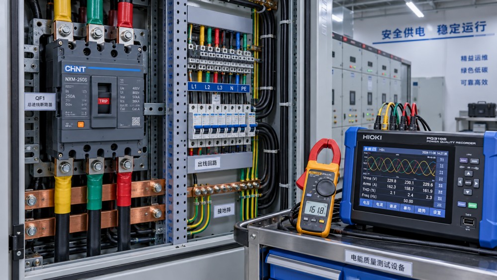
The correct response is not automatically a larger breaker. First, capture the event with a power-quality recorder or meter capable of recording peak and inrush behavior. Compare the measured waveform against the trip function and time-current characteristics. Then review whether loads should be staged, whether a soft starter or drive parameter is appropriate, whether transformer energization sequencing needs adjustment, or whether the protective scheme requires engineering revision.
Coordination problems appear only after the system is energized
Selective coordination means a downstream protective device should clear a local fault before an upstream main device disconnects a wider section of the installation. During commissioning, a coordination issue may show up as an upstream breaker tripping while the branch breaker remains closed, or as two breakers opening for the same event.
Settings cannot be assessed from rating labels alone. The fault current available at each point in the system affects how quickly protective devices respond. Changes to transformer impedance, generator connection, busbar arrangement, cable length, parallel feeders, or utility supply conditions alter available fault current and can invalidate assumptions used in the original study. A feeder that is adequately coordinated on normal utility supply may behave differently when supplied by a generator with lower fault contribution.
Short-time delay and instantaneous pickup require particular care. A delay that improves selectivity must still remain within the thermal and mechanical withstand capability of the equipment and conductors. For this reason, coordination adjustments should be confirmed against the complete protection design rather than made breaker by breaker in the field.
Load changes between testing and occupation
Commissioning loads are often incomplete. Final tenant equipment, kitchen appliances, pumps, server racks, electric heating, battery chargers, controls, and decorative lighting may be connected after initial functional tests. Temporary loads can also distort the picture: construction tools, dehumidifiers, welding equipment, and temporary distribution boards may share circuits intended for permanent building loads.
Measure current on all phase conductors and the neutral during representative operation. An apparently acceptable total current can conceal serious phase imbalance. In three-phase four-wire systems, nonlinear loads can create substantial neutral current through harmonic components. The neutral must be evaluated according to the conductor arrangement and design assumptions; it should not be treated as an inactive return path merely because phase currents look balanced at a glance.
Compare measured demand with the panel schedule, protective settings, conductor size, and the actual diversity of connected equipment. Do not assume that a design diversity factor remains valid after the use of a space changes. A circuit serving general small-power outlets behaves differently when it begins supplying continuous IT equipment or portable process loads.
A disciplined isolation sequence
Before testing, de-energize, lock out, and verify isolation using procedures appropriate to the installation. A breaker that trips may be associated with energized busbars, stored energy, automatic controls, or backfeed sources. The investigation should preserve the original condition as far as possible: document breaker position, trip indication, connected equipment, alarm states, and the precise switching sequence.
- Identify the breaker frame, trip unit, rating plug where fitted, installed settings, and all remote-trip accessories. Confirm that the device matches the approved circuit function and has not been exchanged during construction.
- Separate the downstream circuit into logical sections. Disconnect branch loads where feasible, then energize progressively. A trip that disappears after one branch is isolated narrows the search, but the branch still needs insulation, polarity, termination, and load testing before it is returned to service.
- Measure phase current, neutral current, voltage, and where relevant residual current during the actual switching sequence. Record starting order, transfer events, and automatic restart behavior rather than relying on a single steady-state reading.
- Inspect and test the suspect section with suitable instruments. Include insulation resistance, conductor continuity, protective-conductor continuity, phase identification, torque verification, and thermal observation under controlled load where applicable.
- Review the protection settings and coordination basis after the physical circuit is proven sound. Settings should be changed only with a documented reason and confirmation that conductor and equipment protection remain adequate.
Conditions outside the power path
Some trips are initiated by accessories rather than by overcurrent. An undervoltage release can open the breaker when its control supply drops during transfer, when a control fuse is loose, or when voltage is derived from an unstable auxiliary source. A shunt-trip coil can receive an unintended signal from fire interfaces, emergency shutdown circuits, interlocks, or incorrectly configured controls. The visible result is an open breaker, but no overcurrent condition exists.
Control-circuit diagnosis should include terminal identification, supply voltage under operation, interposing relays, normally open and normally closed contact logic, and the behavior of any automatic transfer or emergency command. Temporary links used during testing must be removed and documented. A latent temporary bypass or wrongly retained jumper can produce a trip long after the electrical installation appears complete.
When the breaker itself is suspect
A defective breaker is possible, although it should not be the first assumption. Evidence becomes stronger when the downstream circuit has been isolated and tested, measured current remains within the verified setting limits, control accessories are excluded, and the same device still trips inconsistently or cannot be reset correctly. Mechanical damage, contamination, incorrect assembly after maintenance, an incompatible trip unit, or a damaged operating mechanism can affect performance.
Replacement should preserve the intended protection characteristics, interrupting capability, accessories, and coordination assumptions. Fitting a device with a higher rating or different trip behavior solely because the original breaker opened can hide a fault and transfer the failure point into cables, busbars, or connected equipment.
Reliable post-commissioning operation comes from matching field measurements to the actual electrical design, including its switching sequence and connected load. Once the trip mechanism is identified, the corrective action becomes narrower: repair a circuit fault, rectify a termination, adjust a documented operating sequence, correct control wiring, or revise protection settings within the system's verified limits.
Power Distribution Architect
Related News
- 00
0000-00
Why Do Circuit Breakers Trip After Commissioning? - 00
0000-00
How to Choose Circuit Breakers for Critical Loads - 00
0000-00
Why Japanese Precision Circuit Breakers Matter in High-Reliability Panels - 00
0000-00
Finding overheating faults in panels before components fail - 00
0000-00
Smart Building MEP Integration: Coordinating HVAC, Power, and Controls to Avoid Rework
Weekly Insights
Stay ahead with our curated technology reports delivered every Monday.